Building Regulations - Are you ready for the Part L changes?
The newest version of Approved Document L1A (2021), which supports Part L of Schedule 1 to the Building Regulations 2010, published in June 2022, has tightened the requirements for an efficient building standard by adjusting several threshold values and by introducing new topics and processes. Particular attention is given to thermal bridging and the relevant changes surrounding this topic. The new changes are presented below, with an outlook to further regulation development also given.
The tightened and partly new evidence requirements will help to ensure that a building is built as energy-efficient as planned. Thereby, one reason for the performance gap (difference between the energy consumption predicted in the design stage and the energy use in operation) will significantly diminish in the future.
Continuity of insulation (section 4.14-4.15)
To ensure continuity of insulation and hereby avoid large heat losses through gaps, the insulation layer should be clearly shown in the design drawings. During an on-site audit the as built construction has to be confirmed according to design and photographic evidence should be provided. Please note that all photographic evidence should be in line with guidance in Appendix B.
Thermal bridging (section 4.16-4.17)
Thermal bridging in the building fabric has to be reasonably limited. Therefore, drawings for junctions should be provided, with photos of thermal-bridging details evidenced during the on-site audit.
Due to concerns about thermal bridging leading to heat losses and condensation, the new regulations state that opportunities should be considered to reduce thermal bridges. Any substitutions of products to minimize thermal bridging, if necessary, should be reflected in the SAP calculation and documented in the BREL report to ensure they are still compliant.
Additional information for new dwellings (section 9.3)
A signed copy (by the developer) of the BREL compliance report and photographic evidence of the build quality should be provided to the building control body and the homeowner to confirm that the building has been completed according to the original specifications.
BREL reports (section 2.4+5, 9.3+4, Appendix B)
Two versions of the BREL report should be produced for the building as a standard output from SAP 10: the design stage BREL report, before works begin and the as-built BREL reports. Both have to include, amongst various other facts, the dwelling primary energy rate, dwelling emission rate and dwelling fabric energy efficiency rate.
The most important subjects are:
| Design stage BREL report | As-built stage BREL report |
|
Supporting list of specifications.
Defining/calculation of heat losses through junctions/thermal bridging.
U-values/PSI-values for thermal breaks. |
Supporting list of specifications, including any changes to the specifications provided at the design stage.
Finalised U-value calculations.
Photographic evidence (see more details below).
Signed by SAP assessor to confirm the as-built calculations are accurate and the supporting documentary evidence and photographs have been reviewed.
Signed by the Developer to confirm that the dwelling has been built according to the specifications and meets compliance. |
Photographic evidence (Appendix B)
Photographs of foundations/ground floor and each external main wall should be made available to the energy assessor and the building control body. Photos should be close-ups where necessary, use geolocation to confirm location, date and time of each image.
Concerning walls, they shall prove thermal continuity and quality of insulation for structural penetrating elements and ground floor to wall junction.
For further information and the original text please visit: Approved Document L, Conservation of fuel and power, Volume 1: Dwellings
Building Regulations Part L includes the requirement that minimum internal surface temperatures be such that condensation risk is minimized and mould growth avoided.
Approved Document L1A (L2A for non-residential buildings) cites the BRE Information Paper IP1/06 (Assessing the effects of thermal bridging at junctions and around openings)
Condensation and mould risk depend on the relative humidity, which is present at the inner surface of the façade or building construction in general. If the temperature of the inner surfaces is below the dewpoint, the room air will here cool down, so that condensation will occur.
For mould growth no condensation is needed, here a relative humidity of about 80% is sufficient to provide conditions which favour development of mould.
If room air is 20°C and 60% RH, the surface temperature of 15.3°C causes 80% RH at the surface of the inner wall.
A measure to describe the relation between inner air temperature, outer air temperature and inner surface temperature is the temperature factor fRsi, which in mentioned in the BRE Information Paper IP1/06.


The minimum temperature factor, which has to be achieved for preventing mould growth, is 0.75 for residential buildings, according to IP1/06. This corresponds to a minimum internal surface temperature of 15°C.
The example below shows a simple steel-to-concrete-connection (without Schöck product), which is not fulfilling the requirements. At the ceiling of the bottom room there is a spot with 14.2°C surface temperature, which corresponds to fRsi = 0.71.
This “cold spot” provides potential for high surface humidity and therefore the risk of mould growth. Mould can issue health implications for the residents. Permanent moisture problems are likely to cause damage to the construction and lead to refurbishment costs.

Sample calculation of a low-performing structural thermal break for a beam-to-slab construction, the blue spot on the indoor ceiling clearly shows an fRsi < 0.75
Details using Schöck thermal breaks show temperature factors far in excess of Part L requirements in all cases. Temperature factors can be calculated by Schöck for bespoke details on request to verify code compliance.
For many constructions our online tool “Thermal Bridging Calculator” can be used to calculate fRsi, minimum surface temperatures and thermal bridge heat loss.
To pass Building Control requirements in England and Wales, it is necessary to demonstrate compliance with Building Regulations. The Building Regulations Part L and associated guidance document for residential construction Approved Document L1A (ADL1A) require that thermal bridging be included in the fabric heat loss calculations.
The latest version of Part L (2021) has raised the requirements for U-values in different categories, which means that the influence of thermal bridges becomes even more important. Some maximum U-values have been decreased, as well as the U-values of the notional building.
The latest version of Part L (2021) has now raised the default additional heat loss through thermal bridges (y-value) from 0.15 to 0.20, which is an increase of 33%. This means that a consideration of thermal bridges in the SAP calculation by default value (4.18 option d) has an unreasonable impact and “punishes” the planner with a high extra heat loss.
Therefore, it is a big advantage in a new building project to deal with thermal bridges in detail (along with 4.18 option a, b or c). The largest potential lies in the detailed thermal bridge calculation (option a), because standard or default values often have some buffer included for being on the safe side.
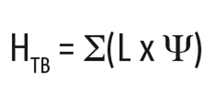
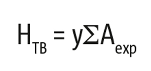
The Government Standard Assessment Procedure (SAP 2012) is the simple energy use and carbon emissions model used to provide evidence that the carbon emissions target has been achieved. The SAP calculation includes the term HTB (heat loss due to thermal bridging) which is calculated or estimated as below:
1) The sum of all linear thermal transmittances (Ψ) x length of thermal bridge in meters (L)

If there are significant point thermal bridges, such as metal components bridging insulation layers (e.g. balcony supports), they have to be added:

n – number of point thermal bridges with thermal transmittance χ
χ – point thermal transmittance of point thermal bridge in [W/K]
2) Using the factor y = 0.20 in the equation below:

(where Aexp = total exposed fabric area)
The calculation of a sample building results in transmission heat losses of 0.39 W/(m²*K) for the building envelope without thermal bridges. If thermal bridges are calculated by default value y=0.20 W/(m²*K) this adds more than 50% of transmission heat losses to it. Compared to the y-value of the notional building of 0.05 W/(m²*K) or the y-value of 0.04 W/(m²*K), which was calculated for the sample building, it can be clearly seen, how large the saving potential is, when thermal bridges are minimized and calculated in detail.
Climate neutrality 2050 has been enshrined in law. It is necessary to keep the global temperature rise in limits and Great Britain internationally wants to prove its pioneering role . Most recently, in 2021, it was determined that CO2-emissions should be reduced by 78 per cent by 2035 compared to 1990. So far, greenhouse gas emissions have been reduced by about half. This has been achieved mainly by abandoning coal-fired power and investing in renewable energies.
Now it is also a question of further reducing CO2-emissions especially from buildings. The current changes in Part L bring about a reduction of 31%. The goal for 2050 is, on the one hand, to make buildings even more efficient and, on the other hand, to convert the heating of buildings to low-carbon. London, part of the C40 Cities Initiative, shows that the targets are very ambitious. Within this C40 group the cities enact policies ensuring new buildings operate at net-zero carbon by 2030 and all buildings by 2050. For the whole of the UK, similar scales must be aimed for.
So the current change is not the end. We are on the way to the "Future home standard", which is targeted for 2025. After that, we can expect further tightening on the way to carbon neutrality in 2050. We expect tighter U-values and regulations on thermal bridges could also become stricter.


